
Most people are familiar with music’s ability to make us move: to tap our feet, bob our heads, or dance to the beat of a groovy tune. However, the precise neural and cognitive mechanisms of the human ability to synchronize with a beat are still uncertain, and are thus an area of active study by neuroscientists and psychologists. One common method for studying human rhythmic abilities in cognitive neuroscience is to ask people to spontaneously tap out a rhythm or to tap along with a beat. One limitation to this method has been the device used: conventional computer human-interface devices (such as keyboards or mice) have poor timing and feel unnatural to tap on. This project — a custom response device and software built on an Arduino platform — is a response to the need for a better tapping device.
The hardware is similar to a drum pad — it consists of a piezo element sandwiched between layers of neoprene, connected via analog input to an Arduino micro-controller. In contrast to a typical drum pad, the exposed surface area surrounding the piezo is damped in order to isolate taps (and ensure reliability across participants for experiments). The software is unique in that it is one of the few attempts to interface between an Arduino and a stimulus-presentation program, E-prime, that is used by many Psychology researchers (but see References, below).
This project has benefited from funding from the NIH to principle investigators Gary Kidd at Indiana University and J. Devin McAuley at Michigan State University. Special thanks are due to David McFarlane, Michigan State’s resident E-Prime expert and more, who was crucial to the development of this project (the meat of both the E-basic and Arduino code was written by him!)
If you have questions about this project, feel free to contact me via the “About” link in the Menu.
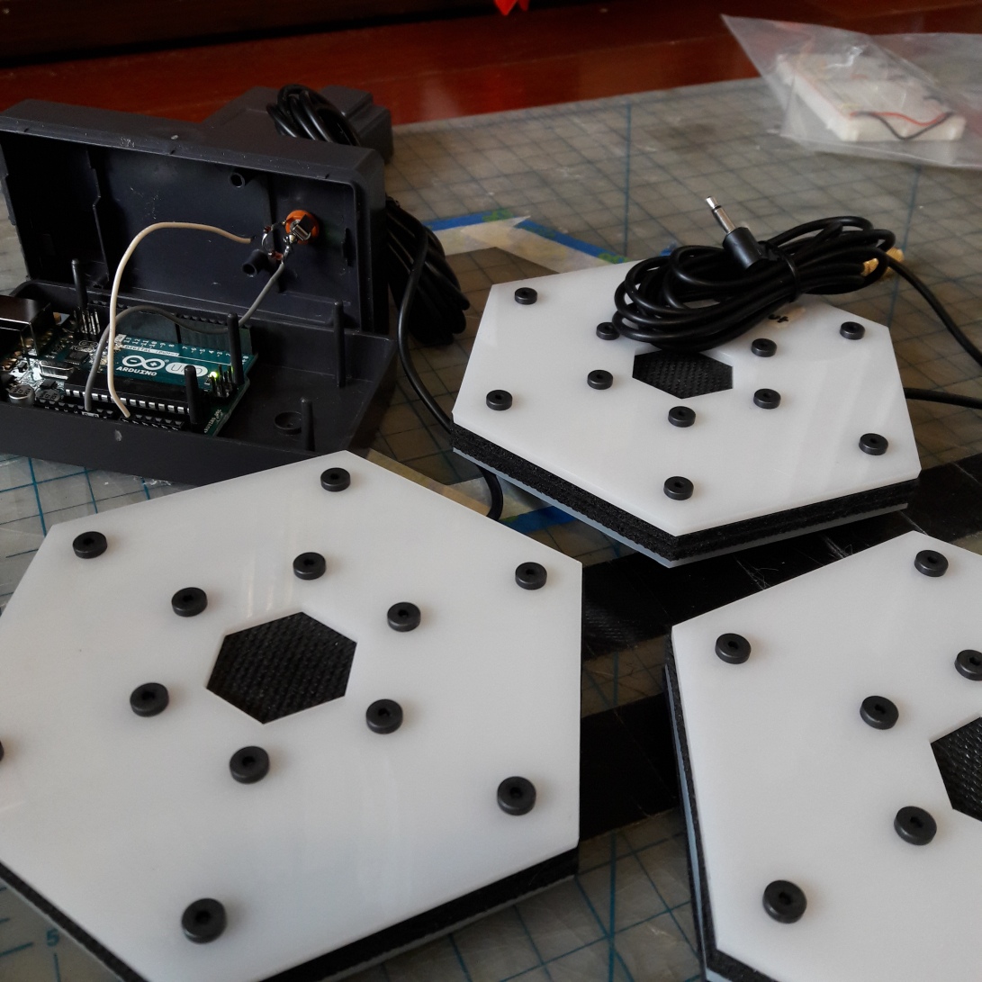
2017 Update: Design modifications to improve damping for “after-taps” — double layer of acrylic with neoprene; improved circuitry between piezo and Arduino. Image below shows three sensors.
Initial design and development: Images (below) of early drawings during development of the device.


References:
Bååth, R. (2011). Construction of a Low Latency Tapping Board. LUCS minor,17, 362-366.
Schubert, T. W., D’Ausilio, A., & Canto, R. (2013). Using Arduino microcontroller boards to measure response latencies. Behavior research methods, 45(4), 1332-1346.
